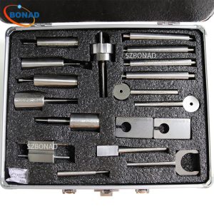
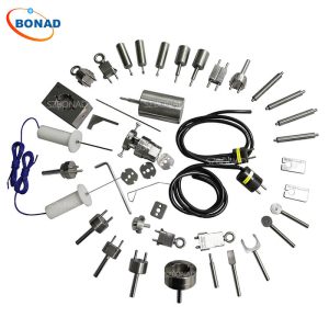
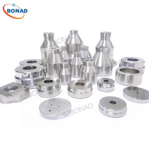
EN50075 Test Gauge and test device
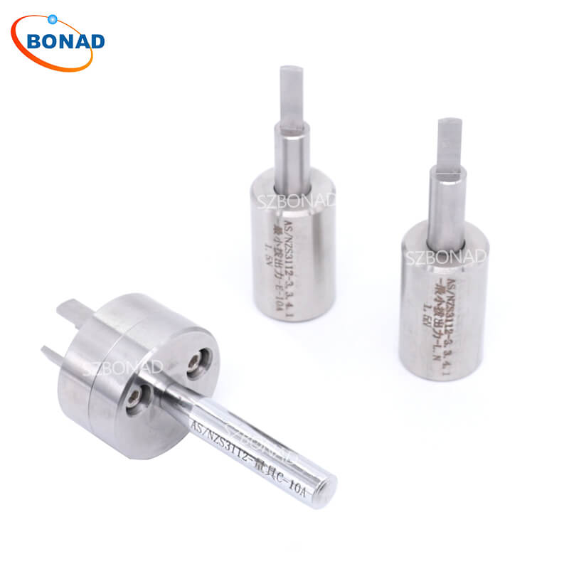
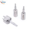
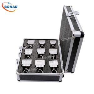
EN 50075 Figure 4 Gauge for Checking Impossibility of Single-pole Insertion of Plugs Into Socket-outlets without Position Rack
Application:
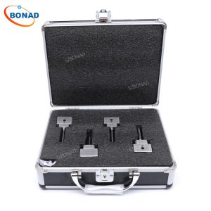
This plug and socket test gauge is mainly used to test and inspect whether the structure and size of plugs and sockets conform to EN 50075:1990 standards. And the mainly application industries is electronics, electrical appliances, plugs and sockets and other similar areas.
| Product name | Standard | |
| 1 | Gauge for pin diameter | EN50075-Fig1-GO |
| 2 | Gauge for pin diameter | EN50075-Fig1-NotGO |
| 3 | Gauge for interchangeability | EN50075-Fig2 |
| 4 | Standard test finger | EN50075-Fig3 |
| 5 | Gauge for checking impossibility of single-pole insertion of plugs into socket-outlets | EN50075-Fig4 |
| 6 | Apparatus for testing cord retention to the accessory | EN50075-Fig5 |
| 7 | Arrangement for compression test | EN50075-Fig7 |
| 8 | Tumbling barrel | EN50075-Fig8 |
| 9 | Apparatus for abrasion test on insulation sleeves of plug pin | EN50075-Fig9 |
| 10 | Apparatus for compression test for the verification of resistance to heat | EN50075-Fig10 |
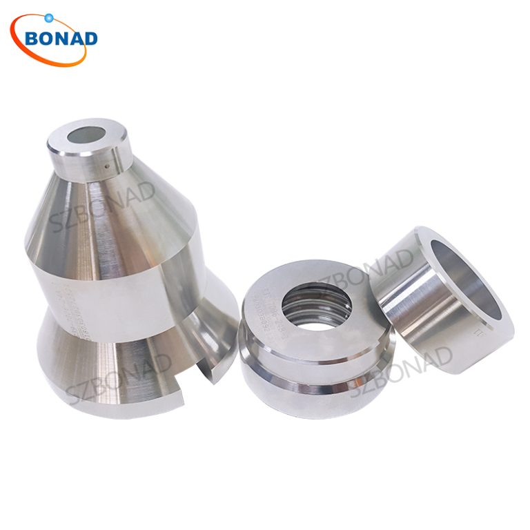
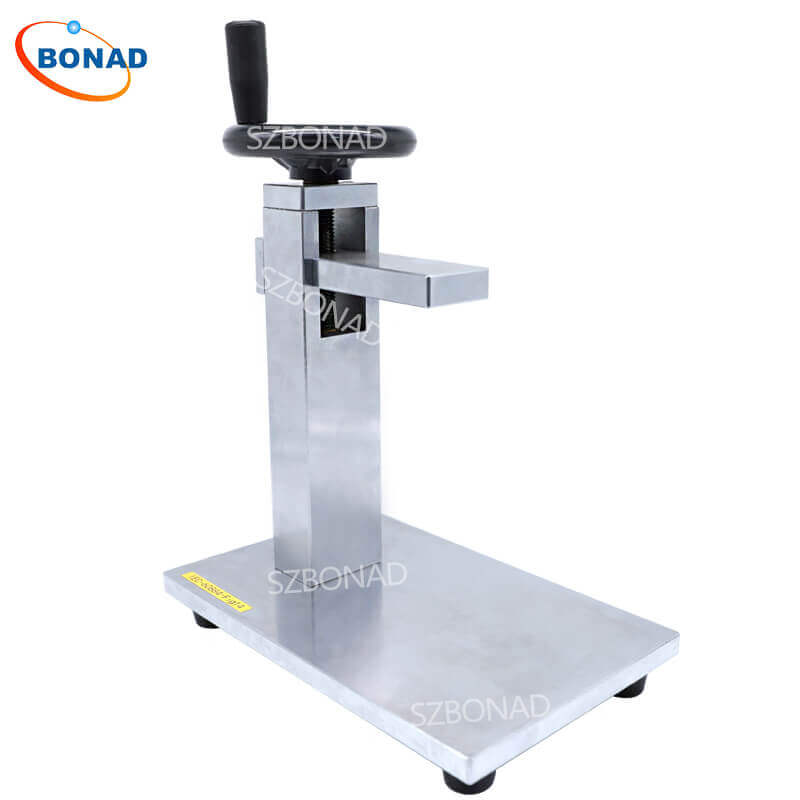
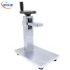
EN50075-13.3 Figure9 Insulation Sleeves of Plug pins Abrasion Test Apparatus.
The insulation sleeves of plug pins abrasion test apparatus is designed and manufactured according to the standard requirement of EN50075-13.3 Figure9. It is used to test the abrasion resistance of the insulating bushing of the bolt.
This device comprises a horizontally disposed beam, which is pivoted about its centre point. A short length of steel wire, 1 mm in diameter and bent into a U-shape, the base of the U being straight, is rigidly attached, at both ends, to one end of the beam, so that the straight part projects below the beam and is parallel to the axis of the beam pivot. The plug is held by a suitable clamp in such a position that the straight part of the steel wire rests on the plug pin, perpendicular to it. The pin slopes downwards at an angle of 10° to the horizontal. The beam is loaded so that the wire exerts a force of 4 N on the pin.The plug is moved backwards and forwards in a horizontal direction in the plane of the axis of the beam, so that the wire rubs along the pin. The length of the pin thus abraded is approximately 9 mm, of which approximately 7 mm is over the insulating sleeve. The number of movements is 20 000 (10 000 in each direction) and the rate of operation is 30 movements per minute. The test is made on one pin of each specimen.

